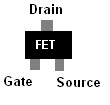
A FET is a Field Effect Transistor. They are very similar to traditional transistors except they offer much better efficiency in most applications. There are many different types of FETs, each with its own use. MOSFETS, JFETs, IGBTs, FREDFETs are just a few examples of the different types. Each has a different composition and different pros and cons. We use MOSFETs to power our motors in the mCP X. From now on I will just refer to them as FETs for simplicity.
FETs are most commonly used as a switch. Just like a switching relay or a car starter solenoid, a transistor allows you to use a very small power source to turn on and off a much higher power source. In a traditional transistor the power used to "flip the switch" is consumed by the circuit. A lot of power is wasted this way. In a FET the transistor only needs to "feel", not consume, the voltage being applied to flip the switch. Almost no power is being used to activate the FET. This results in smaller control circuits, lower power needs, and most importantly for us, longer battery life.
As seen in the picture above there are 3 parts to a FET. There is the Gate, Drain, and Source. A FET can be activated by a positive voltage or a ground depending on how the FET is made. The gate is the input for the positive voltage or ground that switches the FET on and off. The source is the power you want to be switched on and off by the FET. In our helis the source is connected directly to the batteries positive output. The electrical power sits at the source waiting for the gate to let it through. The Drain is the output of the FET. The load is connected to the drain. In our mCP X, the motor is the load and is connected to the drain.
In the simplified circuit above it is easy to tell that the load of the circuit is the motor. With the motor acting as the load, all the energy from the battery is consumed by the motor and turned into motion, heat, sound, and electromagnetic waves. However if you remove the motor and attach the drain to ground the load is lost and now a new load must be found. The electrons do this automatically by picking the part with the most resistance as the load.
Below you can see the shorted FET.
The picture above is a representation of the 3 in 1 circuit when you short out your tail motor wires or have a motor with an internal short. Since the main motor is no longer there to act as a load for the circuit, the FET is now the load. At appx 80mOhm (80X10^-6) of resistance, it is the highest point of resistance in the circuit. Since the FET cant spin, make noise, generate magnetic fields, or produce light, it converts the applied electrical power into heat. The better your batteries are the hotter it gets and the faster it heats up. A 1s battery rated at 30c 300mAh has the ability to produce 4.2 volts at 9 amps. This means the circuit can consume 37.8 watts of power. The amount of power consumed is determined by the resistance of the circuit. At 80mOhm there is very very little resistance in the circuit. This means that almost the entire power potential of the battery is converted directly into heat.
A short while of uncontrolled heating of the FET turns this
Into this
So, how do you keep your FETs from burning? In some cases you don't. There are things that happen in flight and during a unscheduled landing that are beyond your control. However, there are a few things that you can do to help save your board. First thing to do is inspect your motor wires and replace them if they show any signs of wear. The tail motor wires are nothing more than copper with a thin coat of lacquer on them to insulate them from each other. This coating is easily worn off and results in a short circuit. The second step is to change your motors. If a motor is not performing well or does not sound right it needs to be changed. Those two symptoms may be your only signs that something bad is about to happen. Motors can get internal shorts that are the equivalent to connecting 2 bare wires together. I know the motors may seem expensive but it is better to change a $10 part than ruin a $70 part.
I know this explanation may not be technically precise but hopefully it gives a better basic understanding of FETs. If you have any questions or comments please post away and I will do my best to answer them.
If you need a FET to repair your board or would like me to repair it for you, you can always go to http://www.megasmicros.com/ for help.
Kevin


I keep burning up fets after 2 min of flight. Replaced tail motor and wires it happened again any ideas?
ReplyDelete